PSM Tutorial #2-3 : Texture Coordinates
2013-01-22 2:01 AM
In the previous tutorial we went over the concepts of vertices, indices and vertex colors. Now we will go over an important concept : Texture coordinates.
Now we will look at the next set of declarations in the code. As always I will start by including the full code sample.
public class AppMain
{
static protected GraphicsContext graphics;
static ShaderProgram shaderProgram;
static Texture2D texture;

static float[] vertices=new float[12];

static float[] texcoords = {
0.0f, 0.0f,// 0 top left.
0.0f, 1.0f,// 1 bottom left.
1.0f, 0.0f,// 2 top right.
1.0f, 1.0f,// 3 bottom right.
};

static float[] colors = {
1.0f,1.0f,1.0f,1.0f,// 0 top left.
1.0f,1.0f,1.0f,1.0f,// 1 bottom left.
1.0f,1.0f,1.0f,1.0f,// 2 top right.
1.0f,1.0f,1.0f,1.0f,// 3 bottom right.
};

const int indexSize = 4;
static ushort[] indices;

static VertexBuffer vertexBuffer;

// Width of texture.
static float Width;

// Height of texture.
static float Height;

static Matrix4 unitScreenMatrix;

public static void Main (string[] args)
{
Initialize ();

while (true) {
SystemEvents.CheckEvents ();
Update ();
Render ();
}
}

public static void Initialize ()
{
graphics = new GraphicsContext();
ImageRect rectScreen = graphics.Screen.Rectangle;

texture = new Texture2D("/Application/resources/Player.png", false);
shaderProgram = new ShaderProgram("/Application/shaders/Sprite.cgx");
shaderProgram.SetUniformBinding(0, "u_WorldMatrix");

Width = texture.Width;
Height = texture.Height;

vertices[0]=0.0f;// x0
vertices[1]=0.0f;// y0
vertices[2]=0.0f;// z0

vertices[3]=0.0f;// x1
vertices[4]=1.0f;// y1
vertices[5]=0.0f;// z1

vertices[6]=1.0f;// x2
vertices[7]=0.0f;// y2
vertices[8]=0.0f;// z2

vertices[9]=1.0f;// x3
vertices[10]=1.0f;// y3
vertices[11]=0.0f;// z3

indices = new ushort[indexSize];
indices[0] = 0;
indices[1] = 1;
indices[2] = 2;
indices[3] = 3;

//vertex pos,               texture,       color
vertexBuffer = new VertexBuffer(4, indexSize, VertexFormat.Float3, VertexFormat.Float2, VertexFormat.Float4);

vertexBuffer.SetVertices(0, vertices);
vertexBuffer.SetVertices(1, texcoords);
vertexBuffer.SetVertices(2, colors);

vertexBuffer.SetIndices(indices);
graphics.SetVertexBuffer(0, vertexBuffer);

unitScreenMatrix = new Matrix4(
 Width*2.0f/rectScreen.Width,0.0f,    0.0f, 0.0f,
 0.0f,   Height*(-2.0f)/rectScreen.Height,0.0f, 0.0f,
 0.0f,   0.0f, 1.0f, 0.0f,
 -1.0f,  1.0f, 0.0f, 1.0f
);

}

public static void Update ()
{

}

public static void Render ()
{
graphics.Clear();

graphics.SetShaderProgram(shaderProgram);
graphics.SetTexture(0, texture);
shaderProgram.SetUniformValue(0, ref unitScreenMatrix);

graphics.DrawArrays(DrawMode.TriangleStrip, 0, indexSize);

graphics.SwapBuffers();
}
}
Texture coordinates are interesting concept. They define how a 2d image is mapped onto a 3d plane. It’s a concept that is used heavily in both 2d and 3d rendering and is a very useful bit of foundation knowledge.
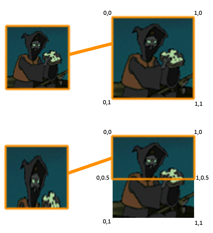
If you want to apply a texture to a plane you need to be able to define how it maps to that plane. As such each vertex requires a extra 2D set of coordinates which define what parts of an image to apply to the plane. UV coordinate space extends from 0 to 1. On the X-Axis of an image file 0 would be the left side of the image and 1 would be the right-most pixel of the image (equal to the width of the image. The concept is the same for the Y-Axis. So if we wanted to show a whole image on a square plane then we would have the following coordinates:
Top left vertex
X = 0 - Y = 0
Bottom left vertex
X = 0 - Y = 1
Top right vertex
X = 1 - Y = 0
Bottom right vertex
X = 1 - Y = 1
Now if you wanted to only show the half top of an image on a plane you would have the following coordinates:
Top left vertex
X = 0 - Y = 0
Bottom left vertex
X = 0 - Y = 0.5
Top right vertex
X = 1 - Y = 0
Bottom right vertex
X = 1 - Y = 0.5
Now nothing helps more than a visual example so here is a image that describes the two situations we have just outlined. Notice the effect of displaying half a square image on a square plane results in stretching distortion.
Now lets take a look at this in code.
static float[] texcoords = {
0.0f, 0.0f,// 0 top left.
0.0f, 1.0f,// 1 bottom left.
1.0f, 0.0f,// 2 top right.
1.0f, 1.0f,// 3 bottom right.
};
Here we have a float array declaration with UV coordinates for each vertex on the quad we wish to draw. As usual this goes counter-clockwise along the vertices. If you compare these declarations to the previous example in this tutorial you most likely will have deduced that a quad with these coordinates will display an entire image.
Before I end this section I would like you to think about some of the uses of displaying the subsection of an image.
- You can use this for animations. Have all your animated frames of a character on one image and “slide” the coordinates each frame over a portion of the image. This is a technique used very frequently for animation. - You can have effects like moving water by moving a sub rectangle over a large image of water.
One last thing Ihaven’taddress is it’s entirely possible to have your texture coordinate ranges outside of the 0-1 coordinate space. The effect this has is different depending on your renderer and settings. One very common usage of this is tiling. If you have a plane whose coordinates extend from 0 to 10 then the image will repeat 10 times across the plane. This is used a lot in 3d rendering for tiling textures like grass or brick.
That’s all there really is to UV coordinates. Next up we will focus on Vertex Buffers.
Tags: psm_tutorial